PMC testing equipment
Troubleshooting and testing of rigs is an important part of the learning curve in CML732 (Model-based control laboratory). This page list some equipment available in the PMC lab to help with this testing.
A rather wise person once said, "Work from knowledge. Break up the testing process into smaller sections."
Control valve testing
With malfunctioning control valves, the problem is usually in one of three areas; the signal sent to the I/P transducer (OPTO 22), the pressure output of the I/P transducer or the valve itself (mechanical problems). The order listed here is in order of increasing effort. Therefore, only screw open your valve as a last resort.
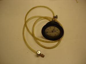
Pressure testing
A little pressure measuring device was assembled to test the output of the I/P transducers. The fittings allow for direct attachment to I/P transducers. 20 kPa should be measured for a low signal (e.g. 4 mA) and 100 kPa for a high signal (e.g. 20 mA). This device can also be used if you need to calibrate your I/P transducer.
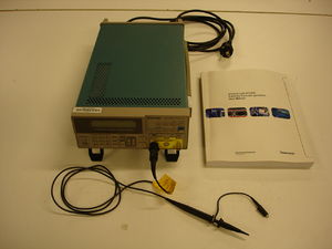
Signal testing
If you suspect OPTO 22 of being the problem, you might want to send custom signals to the valves to test their working. Consult the manual of the signal generator for instructions on using all of its functions. Note that the signal generator outputs a voltage signal. This needs to be converted to a mA signal. The building (and subsequent donating) of this simple circuit to the lab will be greatly appreciated.
The signal generator can also be used to stroke the control valves.

