Double Inverted Pendulum
Introduction
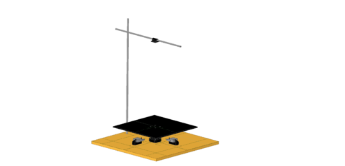
This control rig consists of a cart on a linear rail that can moved in 1D by using DC motor. The cart has a free moving arm attached to it, an angle encoder is used to measure the angle between the cart and the first arm. A second arm is attached to the end of the first arm, a second angle encoder is used to measure the angle between the first and second arm. Where these two angles are used to calculate the control moves to bring to stability.
2020 - Bernard Coetzee
Build
The rig was built by previous students, where the base consists of a wooden board and the rest of the structured is made from polycarbonate sheet.
A Raspberry Pi 3 is used to perform all the input and output operations to and from the process, as well as computational tasks. The inputs to this system consist of the following:
- Distance to end of board, busing a time of flight (IR) sensor
- Angle between the cart and the first arm
- Angle between the first and second arm
These are then used to determine the control moves by moving the cart. This is accomplished by using the DC (MWP) motor.
All control measurement and control operations are carried out using Python 3 on the Raspberry Pi. To control the DC motor an Arduino shield is used.
Modelling
Since this rig is inherently unstable, the system needs to be modelled in order with the aim of moving the zeros from the RHP to the LHP. In this case the MV is the movement of the cart by means of the DC motor, thus the motor's direction and duty cycle. Since this system is non-linear and step test is not a practical method of obtaining a system model, a mathematical model had to be derived from first principals using the Lagrange method. This yielded a state space representation of the system which could be used in Python to implement the controller.
Control Several controllers were implemented with increasing levels of complexity. The first controller was a (PI) Proportional Integral controller, with only the first arm. This was to firstly test and validate all the different component could communication and their values historized, and secondly to get a grip on the controllability of the system. The PI controller worked but had very poor disturbance rejection abilities. Once this was completed, An MPC controller was designed for the single arm, and then for both the single arm and for two arms. It was found that the time required to get the MPC output is to long to be practical
