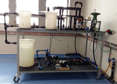
Level and Flow
Introduction
This is the introduction to the level and flow rig wiki page.
Previous Projects
This section describes some of the previous projects that was done on the level and flow rig to give you an idea of what has been done and where you can find the results obtained. Most important data contained in this section is information about what models were used/developed (if you want to reuse models) and what control strategies were employed (if you want to compare your results to something specific).
Francois Pieterse, 2009
Control Strategy: Model Predictive Control making use of ranged control algorithm to minimise MV move effort and optimiser to determine economic operating point.
Model Identification: Manual step testing. Identified models with Honeywell Profit Design Studio.
Models: Linear. Transfer function Matrix. Low Quality.
Rig Problems
As with any design, there are a couple of fundamental problems with the design of the level and flow rig. This section is used to document these problems that, should the need to ever rebuild the rig arise, the persons responsible can have a complete list of all the pitfalls of the previous design so that they can attempt to correct them.
- There was no way to drain the system. A valve to drain the system was included to allow one to remove/replace equipment without causing a spill.
- The level probe was not fixed to the tank 04TK001 that resulted in significant noise in the measurements since the probe was free to move and the discharging flow into the tank resulted in significant turbulence around the level probe. To remedy this positioners were mounted to ensure the level probe remains in position. A false bottom wasalso installed in the tank to minimise saturation of the level measurements.
- The pumps are different. Technically you shouldn't put different sized pumps in parallel although the pumps may have similar charachteristics even though they have different physical sizes.
- The pumps cannot be blocked in or isolated individually. At the time this comment was added the small pump was broken and alot of the head delivered by the big pump was dicipated by recirulating flow through the small pump. The ideal solution is using check valves although this may be unecesarily expensive. Hand valves to block out a pump in the event of failure should be included.
- Upon re-commissioning of the rig after an extended shutdown period it is required to prime the system to achieve flow through the dead time element and into 04TK001. This can be achieved by closing gate valve 04FV001 and filling 04TK003 half with water, stopping the pumps and opening both the control valves fully, 04CV001 and 04CV002. Thereafter the system can be filled with water from the feed pipe into the dead time element. Ensure all other gate valves are in the appropriate position to purge all the air from the system. Upon completion open 04FV001 and start the pumps with a full system.
