PH Rig Maintenance
From Chemical Engineering @ UP wiki
Revision as of 12:33, 10 November 2010 by 137.215.116.248 (Talk)
This page documents the maintenance done as well as changes made to the pH rig. It is important that all changes be noted here as it makes the tracking of scavenged/stolen equipment a little easier.
Pre 2009
Maintenance and changes made to the pH rig before 2009 are not explicitly maintained on the wiki. Consult the project documentation of previous years for said changes.
2009
Wiring/Instrumentation
Wiring of rig found to be in a state of disrepair. An attempt is made to fix all wiring and restore all electronic equipment to a working condition. Fixed equipment/wiring is listed below:
- I/P transducer for control valve 2 and 1 faulty. Replaced both transducers, reconnected piping and wiring.
- Control valve 2 - reconnected piping.
- All the RTDs and temperature transmitters have been removed from the rig (scavenged). Fitted an RTD to each tank and wired to new temperature transmitters.
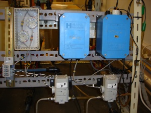
- Housing for temperature transmitters made and fitted to rig (see image).
- Control valve 1 seems to be stuck. Apparently the original valve was removed and replaced by current non-working valve. Valve was opened and oiled and reconnected to new I/P transducer. In working order now.
- Original Signet flow sensor has been removed from rig. A new Burkert flow sensor was fitted to the inlet of tank 3. Old signal conditioner was removed and its power supply removed from the DB. Cable 006 from the DB was wired to the loop power and a Burkert flow transmitter was installed. Unfortunately, both Burkert flow transmitters (brand new) were faulty and the flow measurement has been abandoned due to time constraints.
- Re-fitted pH transmitter 1 and connected a new pH probe.
- PH probe connected to pH transmitter 2 has stopped working. Replaced with working probe. Short wire on new probed forced the cover of pH transmitter 2 to be turned around so as to reach top tank (see image).
- Pump 2 (base pump) was delivering a very low flow when compared to the identical pump 1 (acid pump). The impeller of pump 2 was most likely damaged due to bad decommissioning of the rig. The two pumps were switched so that the 'slower' pump operates on the line which has no control valves.
Piping
Numerous leaks were fixed and connections made where piping has been scavenged off the rig.
Structural
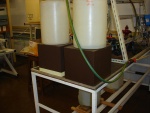
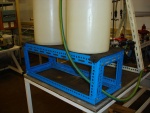
- Stands for feed tanks (currently dustbins) were found to not give sufficient support when tanks are full. Constructed new feed tank stand.
- Fitting of stirrers to tanks found to be flimsy. Versatility of stands (moving them around) outweighed effort to construct new stands. Left as is, but sturdier stands are recommended.
- Rerouted pipe connecting CV001 and FE001 - cut away some of the metal structure to remove strain from pipe.
2010
Wiring/Instrumentation
- Several attempts were made to get the Burkert Flow meter running but there is something wrong with the power supply. It is recommended that professional help is sourced from burkert to setup the flowmeter and get it working.
Piping
- Several random leaks were fixed. Most of these are related to hardening and brittle O-rings. The possibility of acid resistant seals should be investigated.
- The acid feed pipe after the rotameter was rerouted directly into the tank. A handvalve was added before the rotameter to throttle the flow.
- The piping system to load water into the tanks was changed completely. Water can now be added directly into any of the four feed drums to make the feed solutions.
- The waste drum setup was changed to accomodate two drums. It is recommended that a y-fitting be inserted to the waste pipe so that both tanks fill up at the same time.
Systems
- The pH rig computer was formatted and reinstalled with Windows 2003 Server


