Acetone Flashing
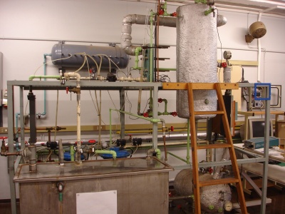
The acetone flashing rig uses a flash drum to separate a mixture of acetone and water.
Contents
Equipment List
- Pumps supplied by J B Stamp
Current/Previous Projects
1999
M.J. Venter, Asetoon Flitsdrom {Acetone Flashdrum}. Hard copy of report available in pH rig folder.
2001
M.J. Venter, Acetone Flash System. Hard copy of report available in pH rig folder. Software Files
2003
G. Ritchie & P.D Nel, Acetone/Water Flash Drum Experiment. Hard copy of report available in pH rig folder. Software Files
2004
S.B. Madolo, Acetone-Water Flash Rig. Report Files | Software Files
2005
- C.D. Brown, Acetone/Water Flash. Hard copy of report available in pH rig folder. Software Files
- N. Mqadi, Modeling and Control of the Acetone-Flash Drum. Report File | Project files
2006
P. Hart & D.F. Grobler, Flash Distillation. [Hard copy of report available in pH rig folder]
2009
L.C. Jones, Modelling and Control of Acetone/Water Flash Distillation. [Hard copy of report available in pH rig folder]
Documentation
Piping & Instrumentation diagrams
Wiring diagrams
Additions to Process Laboratory Handbook
Rig Recommendations
Repair the steel partition between the acetone and the water feed tanks.
Move the water feed control valve from the recycle to the main line.
Investigate the thyristor operation. Input from software signal has no effect on the output of the thyristor power. The ammeter reading on the heater panel remains unchanged.
Install a sight glass onto the flash drum that operates independently of the differential pressure cell. This will allow for easier calibration of the cell and confirmation of the tank level during controller set point changes and disturbances.
The differential pressure cell has an offset to its zero value (mA reading). This reading should be checked using the multimeter and incorporated into the opto.offset .
The electro-pneumatic (E/P) transducers for control valves CV-001 and CV-003 are in good working order. The E/P transducer for CV-002 failed at the end of the module and needs replacing. The E/P transducer for CV-004 does not operate to its full span, a 20 mA signal does not convert to the correct pressure signal to the control valve.
A flash drum level steady state was difficult to achieve. The bottoms flow out of the flash drum was significantly less than what the pumps can supply to the drum. The flow into the drum was minimized by manipulating the drum inlet hand valve HV-005 and the bottoms control valve CV-003 was set at 80% opening to achieve steady state. Assumption made that debris is lying at the bottom of the drum or in bottoms pipe line causing difficulty in emptying the drum.
