Difference between revisions of "PH Loop"
(Adding starting pages for the rigs with rig photos (2 of 6)) |
|||
| Line 1: | Line 1: | ||
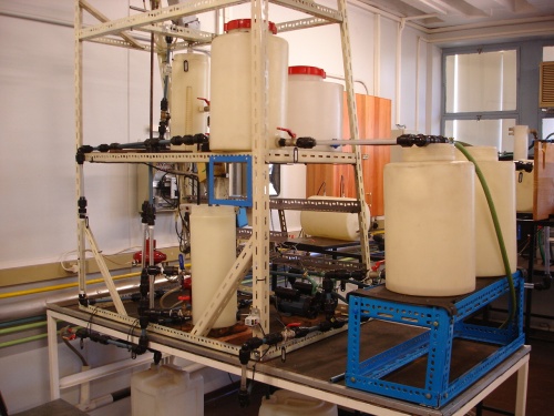
| − | [ | + | [[File:Pmc02ph_rig.JPG|500px|right|thumb|The pH control rig]] |
| − | + | ||
PH control is a difficult problem due to the highly non-linear nature of the system. The steep slope of the titration curve around the pH = 7 point amplifies pH variations for even small base/acid addition variations. The pH control rig in the [[PMC lab]] illustrates that pH control is by no means impossible (albeit on a laboratory scale). | PH control is a difficult problem due to the highly non-linear nature of the system. The steep slope of the titration curve around the pH = 7 point amplifies pH variations for even small base/acid addition variations. The pH control rig in the [[PMC lab]] illustrates that pH control is by no means impossible (albeit on a laboratory scale). | ||
Revision as of 14:38, 10 November 2009
PH control is a difficult problem due to the highly non-linear nature of the system. The steep slope of the titration curve around the pH = 7 point amplifies pH variations for even small base/acid addition variations. The pH control rig in the PMC lab illustrates that pH control is by no means impossible (albeit on a laboratory scale).
Contents
Current/Previous projects
1999
F.J. Botha, Ondersoek van die Dinamiese Gedrag van Sisteme waar pH Gemeet en Beheer word {Investigation of the Dynamic Behaviour of Systems where pH is Measured and Controlled}
[Hard copy of report available in pH rig folder]
2003
T. Leeuw & G. Mascini, pH Rig 2003 - CPL780 Process Control Laboratory
Report | Project files
2005
A.J. Swanepoel & M. Swanepoel (Botha), Model Based Control Laboratory, pH Control
Report | Project files
2007
C. Steyn, Fuzzy Logic Rule-Based Controller Design, Neutralization of Strong Acid with Strong Base
Report | Project files
2009 (Current)
A.H. Campher, project to determine methods of obtaining the attainable- and desired output spaces (AOS and DOS) from a process model.
[Report] | [Project files]
Documentation
Large scale renaming of instruments, valves and tanks are being done. This renders all previous rig diagrams obsolete. Only 2009-updated diagrams should henceforth be used.
Process Flow diagrams
Piping & Instrumentation diagrams
Wiring diagrams
Rig maintenance
Pre 2009
Maintenance and changes made to the pH rig before 2009 are not explicitly maintained on the wiki. Consult the project documentation of previous years for said changes.
2009
Wiring/Instrumentation
Wiring of rig found to be in a state of disrepair. An attempt is made to fix all wiring and restore all electronic equipment to a working condition. Fixed equipment/wiring is listed below:
- I/P transducer for control valve 2 - re-fitted transducer, reconnected piping and wiring.
- Control valve 2 - reconnected piping.
- All the RTDs have been removed from the rig (scavenged?) - in process of replacing them.
- Control valve 1 seems to be stuck. Apparently the original valve was removed and replaced by current non-working valve. In process of testing valve.
Piping
Numerous leaks were fixed and connections made where piping has been scavenged off the rig.
Structural
- Stands for feed tanks (currently dustbins) were found to not give sufficient support when tanks are full. Constructed new feed tank stand.
- Fitting of stirrers to tanks found to be flimsy - refitting them to more sturdy structures.
- Rerouted pipe connecting CV001 and FE001 - cut away some of the metal structure to remove strain from pipe.
