Difference between revisions of "Temperature Control"
(Adding starting pages for the rigs with rig photos (3 of 6)) |
(→2017 - Marcelle de Kock) |
||
| (One intermediate revision by the same user not shown) | |||
| Line 1: | Line 1: | ||
| − | [[File: | + | == Introduction == |
| − | The | + | |
| + | The temperature control rig aims to control the temperature of a process with varying dead-times. The system consists of 4 thermocouples, a radiator and boiler with thyristor. | ||
| + | |||
| + | == Previous Projects == | ||
| + | |||
| + | The previous information for this system is scarce and incomplete, but this section aims to track the changes made to the rig. | ||
| + | |||
| + | === 2017 - Marcelle de Kock === | ||
| + | [[File:New rig picture.jpeg|500px|right|thumb|2017 temperature control rig]] | ||
| + | '''Rebuild''' | ||
| + | |||
| + | The rig was dismantled from the vertical back plate it was mounted on and reconfigured for the two level trolley system. | ||
| + | |||
| + | Still TODO: | ||
| + | |||
| + | The junction box and thyristor still need to be mounted on the wall, however the thermocouple wires are too short. A railing was used to extend the wiring, but caused severe measurement drift. | ||
| + | |||
| + | The water supply of the lab is too powerful for the float valve on the boiler, so a bucket system is currently used to startup the system, and it is assumed that losses due to evaporation are negligible. | ||
| + | |||
| + | The drain valve was removed and the piping does not reach the lab drainage point. Again, a bucket system is currently used for shut down. | ||
| + | |||
| + | '''Instrumentation communication''' | ||
| + | |||
| + | All 4 thermocouples are wired to a Allen-Bradley MicroLogix 1100 PLC thermocouple input unit. An analog output unit for the same PLC is used to send a 4-20mA signal to the thyristor and radiator relay. | ||
| + | KEPServer OPC is used to transfer the measurement data from the PLC to Mintek's StarCS control software. | ||
| + | |||
| + | '''Modelling''' | ||
| + | |||
| + | The thermocouples were calibrated by placing them in ice, boiled and room temperature water. The logged data was then used to determine the linear coefficients of calibration needed to correct the measurements. | ||
| + | |||
| + | The heating dynamics were modelled by stepping the mA signal to the thyristor and logging the rate of temperature change. | ||
| + | |||
| + | An experiment was run where the boiler temperature remained constant, the flow route was changed, the radiator was switched on and the system was left to cool by environmental losses. | ||
| + | This data was exported and used in Matlab's Simulink environment to perform initial parameter estimation of the fundamental mass and energy balance equations. The results were coded into a C++ library that is incorporated in a simulator run in StarCS. | ||
| + | |||
| + | '''Control''' | ||
| + | |||
| + | A Model Predictive Controller with kalman filter state estimator and dynamic real time optimiser was implemented in the StarCS environment to control the boiler inlet temperature to a changing setpoint. | ||
| + | |||
| + | === 2005 - David Phillpotts & Ivan Eggberry === | ||
| + | [[File:Pmc03heat_rig.JPG|500px|left|thumb|2005 temperature control rig]] | ||
| + | |||
| + | |||
| + | |||
| + | |||
| + | |||
| + | |||
| + | |||
| + | |||
| + | |||
| + | |||
| + | |||
| + | |||
| + | |||
| + | |||
| + | |||
| + | |||
| + | |||
| + | |||
| + | |||
| + | |||
| + | |||
| + | |||
| + | |||
| + | |||
| + | |||
| + | |||
| + | |||
| + | |||
| + | |||
| + | |||
| + | === 2003 - Hugo van Niekerk & Luka Masina === | ||
Latest revision as of 14:20, 16 November 2017
Contents
Introduction
The temperature control rig aims to control the temperature of a process with varying dead-times. The system consists of 4 thermocouples, a radiator and boiler with thyristor.
Previous Projects
The previous information for this system is scarce and incomplete, but this section aims to track the changes made to the rig.
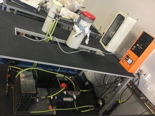
2017 - Marcelle de Kock
Rebuild
The rig was dismantled from the vertical back plate it was mounted on and reconfigured for the two level trolley system.
Still TODO:
The junction box and thyristor still need to be mounted on the wall, however the thermocouple wires are too short. A railing was used to extend the wiring, but caused severe measurement drift.
The water supply of the lab is too powerful for the float valve on the boiler, so a bucket system is currently used to startup the system, and it is assumed that losses due to evaporation are negligible.
The drain valve was removed and the piping does not reach the lab drainage point. Again, a bucket system is currently used for shut down.
Instrumentation communication
All 4 thermocouples are wired to a Allen-Bradley MicroLogix 1100 PLC thermocouple input unit. An analog output unit for the same PLC is used to send a 4-20mA signal to the thyristor and radiator relay. KEPServer OPC is used to transfer the measurement data from the PLC to Mintek's StarCS control software.
Modelling
The thermocouples were calibrated by placing them in ice, boiled and room temperature water. The logged data was then used to determine the linear coefficients of calibration needed to correct the measurements.
The heating dynamics were modelled by stepping the mA signal to the thyristor and logging the rate of temperature change.
An experiment was run where the boiler temperature remained constant, the flow route was changed, the radiator was switched on and the system was left to cool by environmental losses. This data was exported and used in Matlab's Simulink environment to perform initial parameter estimation of the fundamental mass and energy balance equations. The results were coded into a C++ library that is incorporated in a simulator run in StarCS.
Control
A Model Predictive Controller with kalman filter state estimator and dynamic real time optimiser was implemented in the StarCS environment to control the boiler inlet temperature to a changing setpoint.
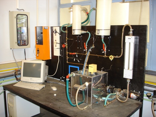
2005 - David Phillpotts & Ivan Eggberry

