Difference between revisions of "Quadcopter"
ShaunVanZyl (Talk | contribs) (→2018 - Jonathan van Niekerk) |
|||
| (5 intermediate revisions by one other user not shown) | |||
| Line 3: | Line 3: | ||
==2018 - Jonathan van Niekerk== | ==2018 - Jonathan van Niekerk== | ||
| + | |||
| + | [[File:QuadRig.png|200px|left|thumb]] | ||
| + | |||
'''Build''' | '''Build''' | ||
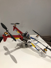
| − | + | The quadcopter is based on a commercially available F450 frame and Arduino Uno controller. A LiPo battery provides flight autonomy of about 15 min and the high current capacity required by the motors. The motors are fitted with 1045 propellers capable of providing the required thrust force to overcome gravity. Electronic speed controllers convert pulse width modulated signals from the Arduino Uno to 3-phase alternating current signals required to drive the motors. The measured angles are derived from a gyroscope and accelerometer mounted on the quadcopter base. The gyroscope and accelerometer needs to be calibrated after power is lost to the inertial measurement unit. The rig is required to prevent the quadcopter from damaging itself during trials, to prevent injury to students and to harness the quadcopter should the control system fail and the system become unstable. | |
| + | |||
| + | '''Modelling''' | ||
| + | The quadcopter is modelled mathematically from angular velocity, Euler kinematic, velocity and position state equations. A linear model is derived based on small angle deviations around the point of equilibrium. Equilibrium is when the roll, pitch and yaw angles are zero. Step test experiments are performed to validate the mathematical model, and curves are fitted to obtain the transfer function models. | ||
| + | |||
| + | '''Control''' | ||
| + | Controllers were designed based on the H-inf mixed sensitivity and SIMC methods. Controllers based on the fitted transfer functions achieved better results that those based on mathematical models. | ||
| + | |||
| + | ==2020 - Shaun van Zyl== | ||
| + | |||
| + | [[File:QuadRig2.png|300px|left|thumb]] | ||
| + | |||
| + | '''Updated Build''' | ||
| + | The Arduino Uno microcontroller was replaced with a more powerful Arduino Uno WiFi Rev2. The | ||
| + | previous external MPU-6050 gyroscope and accelerometer was replaced with the onboard LSM6DS3 | ||
| + | accelerometer and gyroscope chip. This provided the ability to communicate over WiFi using the | ||
| + | UDP protocol, replacing the USB-cable based communications, freeing up the yaw rotation on the | ||
| + | quadcopter. The old rig allowed movement in the pitch, roll and yaw (although the USB cable | ||
| + | prevented yaw movement) directions, while the new one also allows vertical displacement. The new | ||
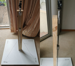
| + | rig consists of a DSLR camera ball joint, a steel rod and some linear bearings. | ||
'''Modelling''' | '''Modelling''' | ||
| − | + | Validation of the previous mathematical model was done with a new literature study. Interestingly, | |
| + | this system requires derivative control to effectively stabilise the double-integrating transfer | ||
| + | functions between the pitch and roll angles, and the motor speeds. | ||
'''Control''' | '''Control''' | ||
| − | + | The new rig and microcontroller posed significant challenges regarding hover stabilisation. The pre- | |
| + | built software used to run the Arduino Uno microcontroller did not run on the Arduino Uno WiFi | ||
| + | Rev2, thus almost all of the software was redeveloped to run with the new hardware. Two notable | ||
| + | PID controllers were attempted on the system with little success, however, the possible | ||
| + | shortcomings of the current software and hardware were identified and possible resolutions were | ||
| + | investigated. A low-pass filter or moving-average filter was used to reduce high-frequency | ||
| + | measurement noise and the effect thereof on the derivative control. | ||
Latest revision as of 10:56, 17 December 2020
Introduction
The quadcopter rig consists of a quadcopter mounted on a stanchion. The control objective is to regulate the speed of the motors to maintain a hover position that is horizontal to the rig's base plate.
2018 - Jonathan van Niekerk
Build The quadcopter is based on a commercially available F450 frame and Arduino Uno controller. A LiPo battery provides flight autonomy of about 15 min and the high current capacity required by the motors. The motors are fitted with 1045 propellers capable of providing the required thrust force to overcome gravity. Electronic speed controllers convert pulse width modulated signals from the Arduino Uno to 3-phase alternating current signals required to drive the motors. The measured angles are derived from a gyroscope and accelerometer mounted on the quadcopter base. The gyroscope and accelerometer needs to be calibrated after power is lost to the inertial measurement unit. The rig is required to prevent the quadcopter from damaging itself during trials, to prevent injury to students and to harness the quadcopter should the control system fail and the system become unstable.
Modelling The quadcopter is modelled mathematically from angular velocity, Euler kinematic, velocity and position state equations. A linear model is derived based on small angle deviations around the point of equilibrium. Equilibrium is when the roll, pitch and yaw angles are zero. Step test experiments are performed to validate the mathematical model, and curves are fitted to obtain the transfer function models.
Control Controllers were designed based on the H-inf mixed sensitivity and SIMC methods. Controllers based on the fitted transfer functions achieved better results that those based on mathematical models.
2020 - Shaun van Zyl
Updated Build The Arduino Uno microcontroller was replaced with a more powerful Arduino Uno WiFi Rev2. The previous external MPU-6050 gyroscope and accelerometer was replaced with the onboard LSM6DS3 accelerometer and gyroscope chip. This provided the ability to communicate over WiFi using the UDP protocol, replacing the USB-cable based communications, freeing up the yaw rotation on the quadcopter. The old rig allowed movement in the pitch, roll and yaw (although the USB cable prevented yaw movement) directions, while the new one also allows vertical displacement. The new rig consists of a DSLR camera ball joint, a steel rod and some linear bearings.
Modelling Validation of the previous mathematical model was done with a new literature study. Interestingly, this system requires derivative control to effectively stabilise the double-integrating transfer functions between the pitch and roll angles, and the motor speeds.
Control The new rig and microcontroller posed significant challenges regarding hover stabilisation. The pre- built software used to run the Arduino Uno microcontroller did not run on the Arduino Uno WiFi Rev2, thus almost all of the software was redeveloped to run with the new hardware. Two notable PID controllers were attempted on the system with little success, however, the possible shortcomings of the current software and hardware were identified and possible resolutions were investigated. A low-pass filter or moving-average filter was used to reduce high-frequency measurement noise and the effect thereof on the derivative control.

